


Three Blade Oil Drill Bit: Cutter Protection Strategies
It is important to keep the blades on a three-blade oil drill bit safe so that drilling goes smoothly and costs stay low in oil and gas activities. Cutter security strategies include choosing the right bit for the job based on the properties of the rock, using the best drilling parameters, using cutting-edge sealing technologies, and following strict upkeep rules. These methods lower the damage caused by abrasive wear, keep heat damage to a minimum, and make PDC cuts last longer. This has a direct effect on entry rates and the total success of the project. By understanding and using these tactics, drilling teams can get the most out of their investments and spend less time on repairs when the ground is hard.
Understanding Three Blade Oil Drill Bits and Their Design Features
The Tri-Blade Cutting Architecture
Tri-blade bits are made with three properly spaced blades that are positioned 120 degrees apart around the bit body. This creates a balanced cutting structure that lowers vibrations while the bit is turning. This set-up spreads the cutting forces evenly across the bit face, which makes it more stable and easier to control the cutting direction, especially in medium-hard rock types like sandstones and limestones. The shape makes it easy for rock chips to be sucked out through bigger junk slots than with multi-blade options. This keeps chips from building up and causing premature wear.
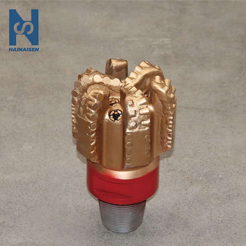
This design theory is shown by our IADC S433 model, which has a 6-inch (152.4mm) bit block with 61 carefully placed PDC cuts. Each 13mm edge is put exactly where it needs to be to get the best cutting results while keeping the structure strong. The bit's outermost cuts, which are exposed to the most contact stress during drilling, are well protected by the 220mm height and 65mm gauge length.
Advanced Cutter Materials and Coatings
PDC cutters are the latest and greatest in drilling technology. They combine synthetic diamond layers with tungsten carbide surfaces to make cutters that are very hard and don't wear down easily. The diamond layer keeps the edge sharp even after thousands of turns, and the carbide base makes it tough so it can handle contact forces without breaking. Modern production methods make a metallic link between these layers that keeps them from coming apart when the temperature changes.
Coating methods add another level of protection. Manufacturers use special heat shields or diamond-enhanced surface processes to lower the friction between the cuts and the formation. These coats better get rid of heat, which keeps cutting temperatures within safe limits. Controlling the temperature is very important because too much heat damages the diamond-carbide contact and makes wear rates go up by a factor of ten.
Integrated Protection Systems
And the bit part itself is the main thing that protects cuts. When cutting aggressively, high-grade steel alloys or tungsten carbide matrix materials protect cuts from side hits and support the structure. Our S433 model has three spray holes that send pressure drilling fluid straight to the cutting face. This creates a hydraulic cleaning action that removes the cuttings and cools the cutters at the same time.
Integrity of the connection is just as important. The 3-1/2 REG.PIN link on our bit makes sure that the drill string can reliably send force to the bit without coming loose when it's turned. A strong link stops the machine from shaking, which would put cuts under uneven load and speed up edge chipping. At 22 kilograms, the bit weight is a good mix between sturdiness and ease of handling. This means that workers can easily install and remove bits without the need for special moving gear.

Common Cutter Wear Challenges and Causes
Abrasive and Erosive Wear Patterns
Abrasion occurs when hard mineral grains in the formation act like grinding particles against the cutter surface. Sandstones containing quartz crystals particularly accelerate this wear mode, gradually dulling the diamond cutting edge. The wear rate correlates directly with formation hardness and the concentration of abrasive minerals. Bits operating in highly abrasive environments can lose millimeters of cutter material over just a few drilling hours if parameters remain unoptimized.
Erosion presents a different challenge. High-velocity drilling fluid carrying rock fragments creates a sandblasting effect on cutter surfaces and bit body components. This fluid-driven wear concentrates around nozzle outlets and in areas where flow patterns create turbulence. While necessary for cutting removal, improperly balanced fluid systems can transform a protective mechanism into a destructive force.
Mechanical Fatigue and Thermal Degradation
Cyclic loading induces fatigue cracks in cutter materials over time in three-blade oil drill bit applications. Each rotation subjects cutters to compression as they engage the formation, followed by tension as they break free. This repetitive stress-strain cycling eventually nucleates microscopic cracks that propagate through the diamond layer or along the diamond-carbide interface. Fatigue failures manifest suddenly, with cutters fracturing catastrophically rather than wearing gradually.
Thermal damage emerges when inadequate cooling allows cutter temperatures to exceed critical thresholds. Diamond begins graphitizing above 700°C, losing its hardness advantage. The tungsten carbide substrate softens at elevated temperatures, reducing impact resistance. Thermal cycling also creates differential expansion between the diamond and carbide layers, stressing their bond. Drilling operations that combine high RPM with insufficient fluid circulation generate the thermal conditions that destroy cutters prematurely.
Root Causes of Premature Cutter Failure
Incorrect bit selection accounts for numerous cutter failures. Deploying a bit designed for soft formations into hard rock subjects, cutters to loads exceeding their design limits. The cutters chip and fracture rather than shearing through the formation cleanly. Conversely, using aggressive bits in soft formations can cause cutters to dig too deeply, creating excessive torque that damages the bit body or connection.
Parameter mismanagement compounds selection errors. Excessive weight on bits crushes cutters against the formation, while insufficient weight prevents effective cutting and causes skidding and wear. RPM settings outside the optimal range for a given formation generate either impact damage from bouncing or thermal damage from friction. Studies show that maintaining RPM between 120 and 220 and carefully adjusting the weight on bit according to formation response can extend cutter life by 40-60% compared to poorly controlled operations.
Proven Cutter Protection Strategies to Maximize Bit Life
Formation-Specific Bit Selection
Matching bit characteristics to geological conditions forms the foundation of cutter protection. Medium-hardness interbedded formations benefit most from three-blade configurations, which transition smoothly between hard and soft layers without excessive vibration. The reduced blade count compared to five-blade alternatives decreases torque fluctuations during directional drilling, protecting cutters from sudden loading changes that cause chipping.
Analyzing offset well data reveals formation tendencies before drilling commences. Historical records indicating high abrasiveness suggest specifying bits with enhanced cutter coatings and conservative cutter exposure angles. Formations known for unpredictable hardness streaks warrant bits with reinforced gauge protection to safeguard the most vulnerable cutters. This proactive approach prevents mismatches that lead to rapid cutter degradation.
Optimizing Operational Parameters
Drilling parameter optimization requires continuous monitoring and adjustment based on real-time bit response. Weight on bit should increase gradually until penetration rate improves noticeably, then stabilize at that level rather than pushing further into diminishing returns. This approach maintains cutters in their efficient shearing mode rather than crushing mode, which generates less heat and reduces mechanical stress.
RPM selection depends on formation hardness and bit diameter. Our 6-inch S433 PDC bit model performs between 140 and 200 RPM optimally in typical medium-hardness formations. Lower RPM suits harder rock to prevent impact damage, while higher RPM accelerates penetration in softer zones. Monitoring torque and drag indicators helps identify when cutters begin struggling, signaling the need for parameter adjustment before damage occurs.
Hydraulic management deserves equal attention. Maintaining a sufficient flow rate through the three nozzles ensures adequate cutting removal and cooling. Insufficient flow allows cuttings to recirculate beneath the bit, creating a grinding paste that accelerates abrasive wear. Nozzle sizing should produce jet velocities that clean the bit face without eroding bit body components. Calculating the proper balance between flow rate and pressure drop optimizes both cleaning and cooling functions.
Advanced Maintenance and Handling Protocols
Regular bit inspections catch wear progression before catastrophic failure occurs. Pulling the bit every 50-80 drilling hours for detailed examination allows crews to assess cutter condition, identify abnormal wear patterns, and decide whether to continue running or retire the bit. Catching damage early prevents total cutter loss that could necessitate time-consuming bit trips or sidetrack operations.
Storage and transportation protocols preserve cutter integrity between uses. Bits should be stored in protective containers that prevent impact damage to cutters during movement. Keeping bits clean and dry prevents corrosion of steel components and contamination of bearing assemblies. Before deployment, verifying the connection thread condition and applying the proper thread compound prevents connection failures that would expose cutters to destructive vibration.
Temperature management extends beyond drilling operations. Allowing bits to cool gradually after pulling from the hole prevents thermal shock that can crack cutter materials. Rapid temperature changes create internal stresses in the diamond-carbide interface that weaken the bond over time. This consideration proves particularly important when drilling in high-temperature formations where bottom-hole temperatures exceed 150°C.
Comparing Cutter Protection: Three Blades vs. Other Drill Bits
Three-Blade Advantages in Specific Applications
Tri-blade bits exhibit cutter protection advantages in directional and horizontal drilling applications. The reduced blade count creates lower reactive torque compared to four or five-blade designs, allowing smoother steering responses. This controlled torque environment protects cutters from sudden loading spikes when the bit changes direction. The larger junk slots between blades facilitate cuttings transport in horizontal sections where gravity cannot assist debris removal.
Stability characteristics also favor tri-blade configurations in moderately consolidated formations. The balanced geometry minimizes lateral vibration that causes cutters to repeatedly impact the borehole wall. This vibration reduction proves particularly valuable when drilling through interbedded zones where alternating hard and soft layers would otherwise induce stick-slip oscillations that damage cutters through cyclic loading.
Trade-offs with Alternative Bit Types
Five-blade bits provide more aggressive cutting action and higher penetration rates in uniform soft formations, but this aggressiveness exposes cutters to greater impact forces. The additional blades reduce individual cutter engagement time, which can benefit cooling in some scenarios. Yet the increased blade count also restricts junk slot size, potentially causing cutting accumulation that accelerates abrasive wear. Choosing between three and five blades involves weighing penetration speed against cutter longevity for specific formation profiles.
Tri-cone roller bits offer superior durability in extremely hard or fractured formations where PDC bit cutters would chip excessively. The rolling cutting action distributes impact forces across bearing assemblies rather than individual cutters. This approach excels in unpredictable geology with hard stringers that would shatter fixed cutters. However, tri-cone bits penetrate more slowly and require more complex bearing maintenance compared to the simpler PDC design. For medium-hardness formations, PDC tri-blade bits deliver better overall economics through faster drilling and simplified maintenance requirements.
Conclusion
Effective cutter protection strategies for three-blade oil drill bits combine thoughtful design selection, parameter optimization, and diligent maintenance practices. Understanding how tri-blade geometry influences cutter wear patterns enables drilling teams to match bits to formation characteristics accurately. Implementing proven operational practices, including controlled weight on bit and optimized RPM ranges, extends cutter life substantially while maintaining competitive penetration rates. Regular inspection and proper handling preserve bit integrity between runs. These integrated approaches reduce drilling costs, minimize non-productive time, and improve overall project economics across oil and gas, coal mining, and water well applications.
FAQ
1. How does tri-blade design improve cutter lifespan compared to other configurations?
The three-blade configuration distributes cutting forces evenly across fewer individual blades, which allows each blade to accommodate more and larger cutters in protected positions. The 120-degree spacing creates balanced loading that reduces vibration-induced fatigue. Larger junk slots between blades improve cutting evacuation, preventing the abrasive recirculation that accelerates wear. This geometry particularly benefits directional drilling by minimizing reactive torque fluctuations that expose cutters to damaging load cycles.
2. What maintenance steps prevent cutter damage most effectively?
Implementing regular inspection intervals every 50-80 drilling hours catches wear progression before failure occurs. Cleaning bits thoroughly after each run removes formation debris that could cause corrosion or obscure damage during inspection. Verifying proper storage conditions prevents impact damage during transportation. Monitoring drilling parameters in real-time and adjusting weight on bit and RPM according to formation response keeps cutters operating within their design envelope, avoiding the excessive loading that causes chipping and thermal damage.
3. Can three-blade bits be customized for specific drilling environments?
Reputable manufacturers offer extensive customization options for cutter size, quantity, placement, and coating selection based on formation characteristics. Hydraulic design customization includes nozzle quantity, size, and positioning to optimize cleaning and cooling for specific mud systems. Bit body materials, gauge length, and connection types can be specified to match drilling equipment and operational requirements. Custom design processes typically involve collaborative analysis of offset well data and formation samples to optimize cutter protection for anticipated conditions.
Partner with HNS for Superior Three Blade Oil Drill Bit Solutions
Drilling operations demand equipment that delivers consistent performance while controlling operational costs through extended service life. Shaanxi Hainaisen Petroleum Technology Co., Ltd. manufactures precision-engineered drill bits in our 3,500-square-meter facility equipped with 5-axis machining centers and advanced production systems. Our dedicated research team designs custom solutions tailored to your specific formation challenges, optimizing cutter protection for maximum bit life. As an experienced Three Blade Oil Drill Bit manufacturer, we serve oil service companies, coal mining operations, and water well drilling teams throughout North America. Contact our technical team at hainaisen@hnsdrillbit.com to discuss your drilling requirements and discover how our application expertise reduces your per-meter drilling costs while improving penetration rates.
References
1. Bellin, F. & Dourfaye, A. (2019). "PDC Bit Technology for the 21st Century." SPE Drilling & Completion Journal, 34(2), 145-162.
2. Hareland, G. & Rampersad, P. (2018). "Drilling Engineering Principles and Practices for Unconventional Reservoirs." Gulf Professional Publishing, Houston, TX.
3. Ledgerwood, L. W. (2020). "Downhole Drilling Tools: Theory and Practice for Engineers and Students." Oxford University Press, Oxford, UK.
4. Menand, S., Sellami, H., & Simon, C. (2016). "PDC Bit Performance Optimization Through Advanced Cutter Technology and Hydraulic Design." International Petroleum Technology Conference Proceedings, Bangkok, Thailand.
5. Pessier, R. C. & Fear, M. J. (2017). "Quantifying Common Drilling Problems with Mechanical Specific Energy and a Bit-Specific Coefficient of Sliding Friction." Society of Petroleum Engineers Annual Technical Conference, San Antonio, TX.
6. Warren, T. M. & Armagost, W. K. (2015). "Laboratory Drilling Performance of PDC Bits." SPE Drilling Engineering Journal, 3(2), 125-135.
 VIEW MORE6-Blade PDC Drill Bit
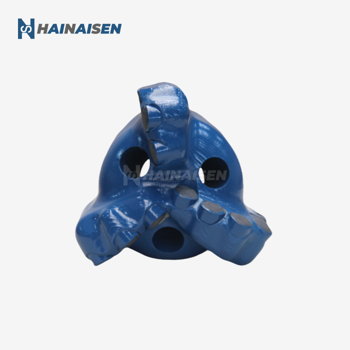 VIEW MORE113mm Three Wing Arc Angle Drill Bit
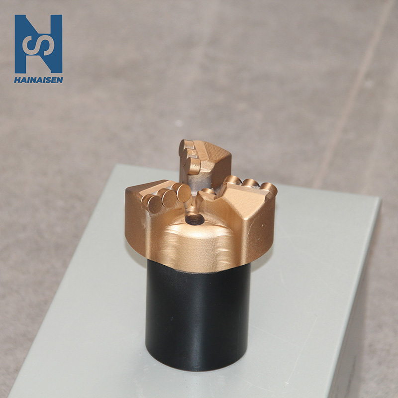 VIEW MOREThree Blades Steel Body PDC Bit
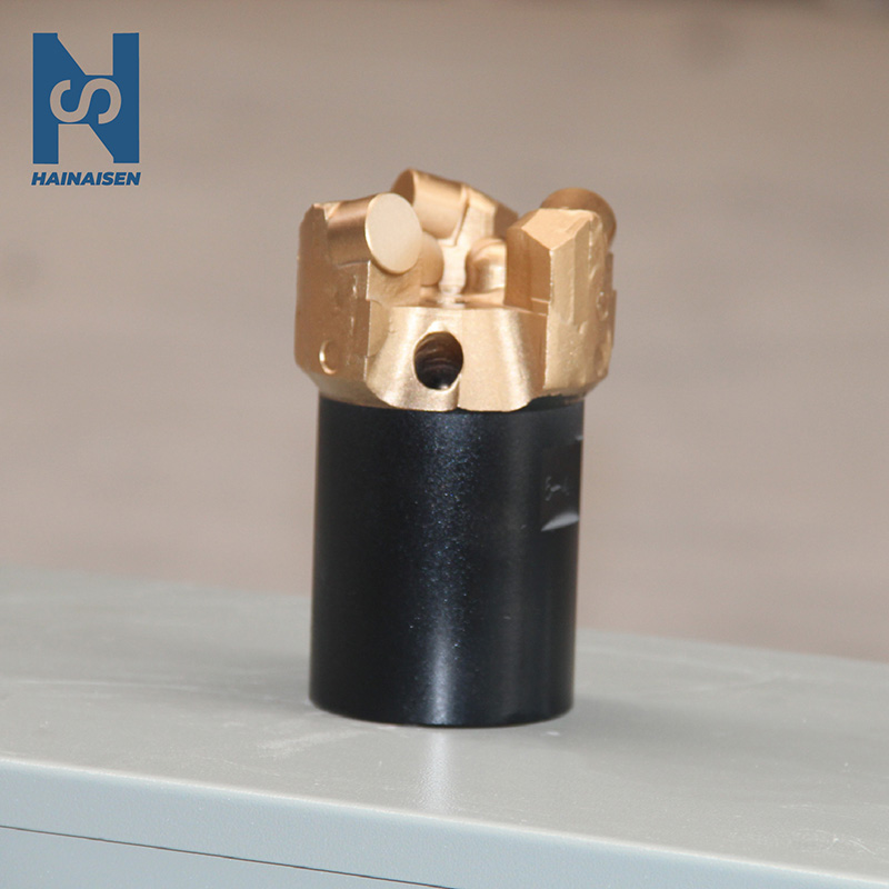 VIEW MORECoal Mining Use Diamond Drill Bit
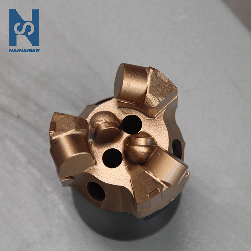 VIEW MORECoal Mines Use Haineisen PDC Drill Bits
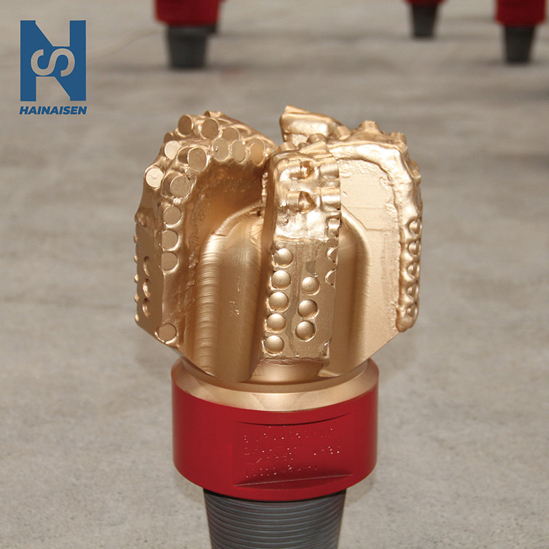 VIEW MORE5 Blades PDC Oil Bit
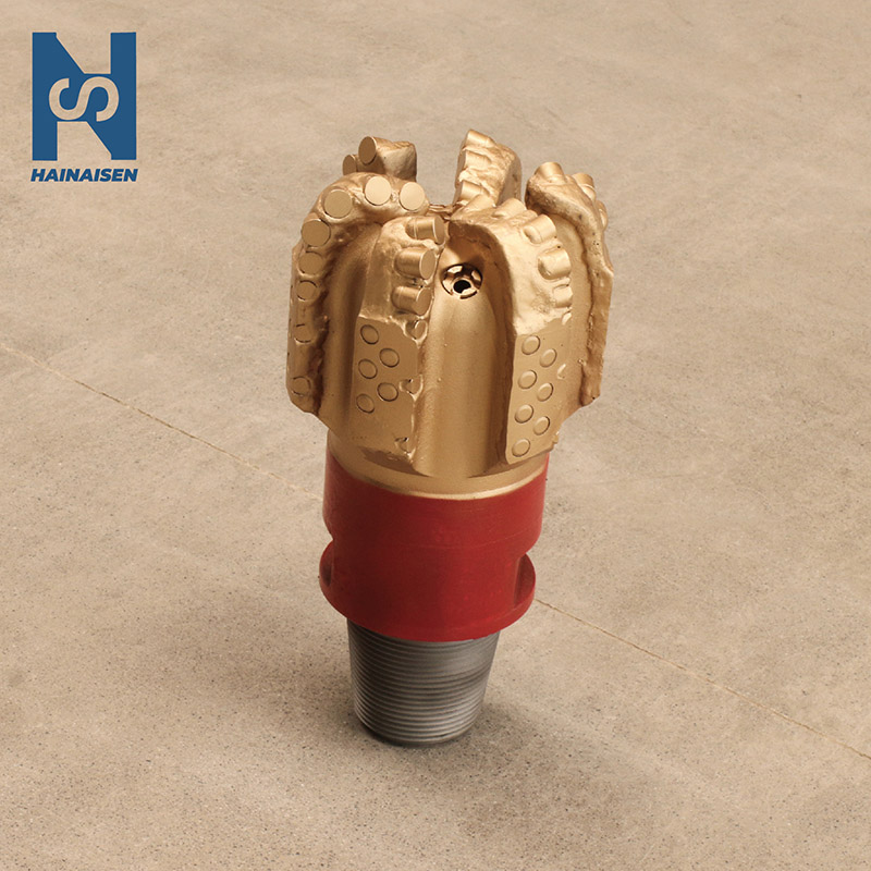 VIEW MORETool 6 Wings Drill Bit PDC
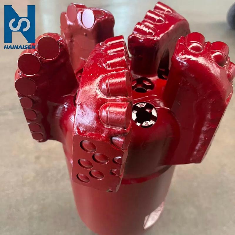 VIEW MORE5 Blade Steel Body PDC Bit