




Why Do PDC Cutters Delaminate? Causes and Prevention of Ring-Outs and Broken Teeth
Contact Hainaisen
Email: hainaisen@hnsdrillbit.com
Tel: +86 17791389758
When a Diamond Oil Drill Bit returns from a drilling run with missing cutters, fractured diamond tables or visible separation between the diamond layer and carbide substrate, the problem is often more complicated than ordinary cutter wear. Delamination, ring-outs and broken cutting elements can result from excessive mechanical loading, thermal stress, poor cutter placement or a mismatch between the bit design and formation conditions. Identifying the actual failure mechanism is essential to preventing repeated damage and unnecessary replacement costs.
PDC cutters are designed to withstand demanding drilling conditions, but their durability depends on the interaction between diamond-table quality, tungsten carbide substrate properties, bonding integrity and downhole operating parameters. Even a high-quality cutter can fail prematurely when exposed to severe impact, excessive frictional heat or unstable drilling conditions.
This article examines why PDC cutters delaminate, how ring-outs and broken teeth develop, and what Manufacturers and drilling engineers can do to reduce these failures through better cutter selection, bit design and drilling practices.
1. What Causes PDC Cutter Delamination, Ring-Outs and Broken Teeth?
Understanding PDC Cutter Delamination
A conventional PDC cutter consists of two primary components:
- Polycrystalline diamond table: The superhard cutting layer that contacts and shears the formation.
- Tungsten carbide substrate: The supporting structure that provides mechanical strength and connects the cutter to the bit body.
These materials are bonded together under high-pressure, high-temperature (HPHT) manufacturing conditions.
Delamination occurs when the diamond table separates from the carbide substrate, either partially or across a significant portion of the interface. In some cases, the diamond layer develops cracks or spalls before complete separation occurs.
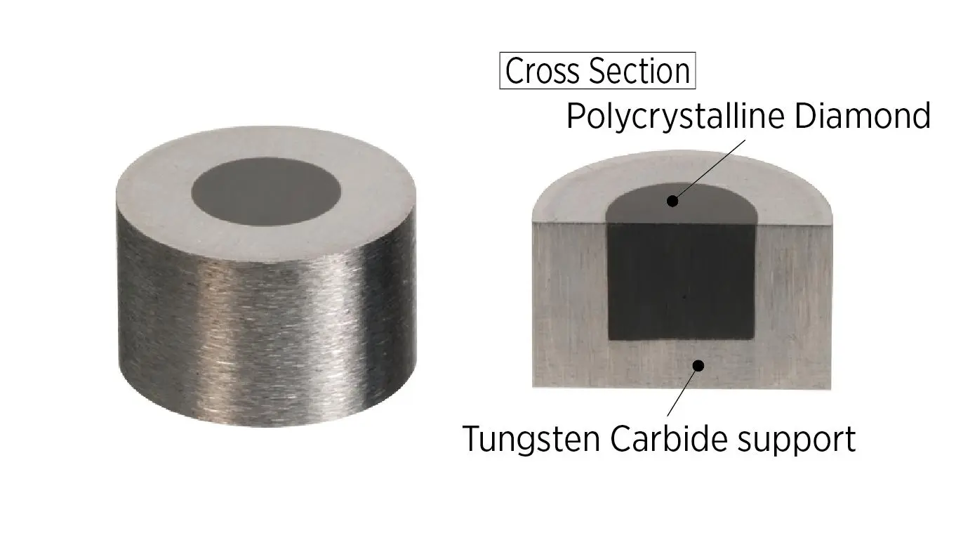
Typical PDC cutter construction: diamond table, bonding interface and tungsten carbide substrate.
One important cause is residual thermal stress. Diamond and tungsten carbide have different coefficients of thermal expansion. During manufacturing and subsequent cooling, this difference creates internal stress within the composite structure.
When additional heat and mechanical loads develop during drilling, existing stress concentrations may become more severe. If the local stress exceeds the strength of the interface or surrounding diamond material, cracks can initiate and propagate.
Research published in the journal Wear identified four major PDC cutter failure mechanisms: smooth wear, micro-chipping, gross fracture and delamination. The study associated interfacial delamination with impact loading and thermal stress caused by the mismatch in thermal expansion between the diamond layer and carbide substrate.
Why Thermal Damage Accelerates Cutter Failure
Frictional heat develops as cutters shear rock and interact with the formation. The problem becomes more serious when:
- The cutter has developed a large wear flat.
- RPM is excessive for the formation and cutting structure.
- Drilling fluid cannot adequately cool the cutting structure.
- Cuttings accumulate around the bit face.
- Stick-slip vibration produces repeated thermal cycling.
At elevated temperatures, diamond degradation can accelerate, particularly when catalytic metal binders such as cobalt are present in the diamond structure.
Thermal damage may appear as progressive surface degradation, edge spalling or characteristic crack patterns. These signs should not automatically be classified as manufacturing defects.
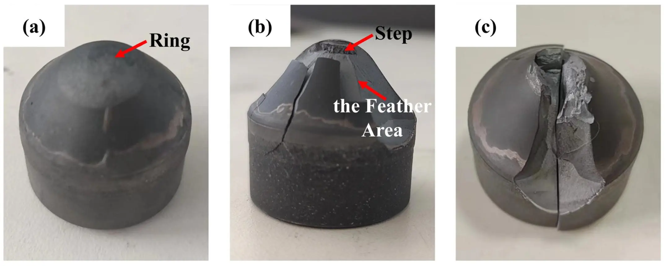
Example of ring-shaped spallation and fracture features in a diamond composite cutting element.
A 2026 study published in the Journal of Composites Science examined residual stress, chamfer spalling, thermal shock and wear in PDC cutters. Its findings reinforce the importance of controlling stress concentrations and improving the thermal and mechanical durability of the cutting surface.
What Is a Ring-Out?
A ring-out is a bit-level failure pattern in which a sequence or spiral of cutters becomes missing along the blades, often around the shoulder and nose regions.
It is not simply another name for individual cutter delamination.
The distinction matters because ring-out can develop through several connected failure mechanisms:
- Cutters in highly loaded positions begin to wear or fail.
- Adjacent cutters receive a greater share of the cutting load.
- Increased loading accelerates impact damage and cutter breakage.
- Additional cutters fail, creating a progressive loss of the cutting structure.
The nose and shoulder are particularly vulnerable because they experience substantial rock-cutting loads and high relative cutting velocities.
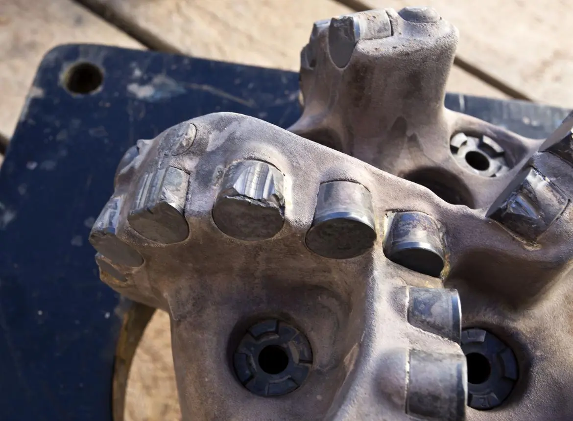
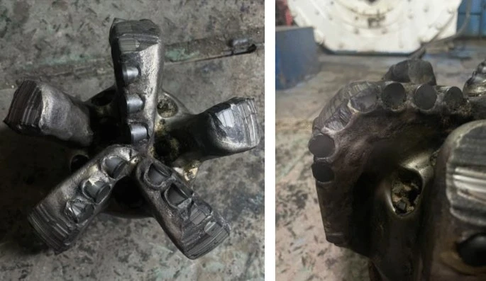
Example of a worn PDC bit after drilling, illustrating why individual cutter condition and blade-level damage patterns need to be inspected.
A 2024 paper presented at the New Zealand Geothermal Workshop describes ring-out associated with insufficient diamond volume in the nose and shoulder, excessive WOB and unsuitable cutter toughness. It also discusses how delamination and impact damage can affect neighboring cutters after the cutting structure begins to deteriorate.
International Geothermal Association
Why Do PDC Teeth Break?
Broken cutters and broken teeth can result from excessive mechanical stress rather than thermal damage alone.
Common contributing factors include:
- Excessive WOB: Too much weight concentrates force on individual cutters.
- Hard formation transitions: Abrupt changes from soft shale to hard sandstone create sudden loading changes.
- Formation impact: Fractured rock and hard inclusions produce intermittent shocks.
- Poor cutter positioning: Insufficient support or unsuitable back-rake angles can increase local stress.
- Drilling vibration: Stick-slip and lateral vibration increase cyclic mechanical loading.
- Foreign objects: Metal debris or other downhole junk can cause severe impact damage.
A useful distinction is the appearance of the failed cutter. A fractured diamond table, a missing cutter, an interface separation and a worn cutting edge indicate different problems. Treating every damaged cutter as a simple material-quality issue can lead to the wrong corrective action.
2. How to Prevent Delamination Through Better Bit Design and Drilling Control
Preventing cutter failure requires a combination of appropriate material selection, mechanical design and controlled drilling parameters. Replacing damaged cutters with a supposedly stronger grade will not solve the problem if the original cause is excessive loading or poor cooling.
Select Cutter Grades According to Formation Conditions
The correct cutter grade depends on the balance between formation abrasiveness and impact severity.
Drilling condition | Main failure risk | Recommended approach |
|---|---|---|
Abrasive sandstone | Thermal wear and diamond-table degradation | Prioritize wear resistance and thermal stability |
Hard limestone | High cutting forces and edge chipping | Evaluate impact-resistant cutter grades |
Interbedded shale and sandstone | Intermittent impact and fracture | Balance toughness with abrasion resistance |
Hard, fractured formations | Gross fracture and cutter loss | Consider stronger cutting structures and impact protection |
Deep, high-temperature wells | Thermal degradation and interface stress | Evaluate thermally stable diamond materials |
For a Diamond Oil Drill Bit, selecting cutters based only on nominal hardness or diamond-table thickness is insufficient. Engineers should also consider substrate support, bonding integrity, chamfer geometry and the expected load distribution.
Optimize Cutter Size, Back Rake and Blade Configuration
Cutter size affects the amount of rock removed during each contact. Larger cutters can provide greater cutting aggressiveness, but they may also experience higher individual loads depending on their exposure and placement.
Smaller cutters, or a denser cutting structure, can distribute the cutting workload across more contact points. This can improve durability, although it may reduce aggressiveness if the design becomes too conservative.
Back-rake angle also deserves attention.
- A more aggressive back-rake configuration generally improves cutting efficiency but can increase mechanical loading.
- A more conservative configuration can reduce cutter exposure and improve impact protection, although excessive back rake may lower ROP.
- The nose and shoulder may require different cutter grades, sizes and orientations from the central cutting area.
The design objective should be to distribute cutting loads without creating concentrated stress at individual cutters or along the diamond-to-carbide interface.
Improve Hydraulic Design and Hole Cleaning
Hydraulic performance is sometimes overlooked when investigating cutter damage.
Insufficient fluid flow can allow cuttings to accumulate around the bit face. This increases the possibility of recutting, frictional heating and localized loading.
An effective hydraulic design should provide:
- Adequate fluid flow across the cutting structure.
- Effective cleaning around the nose and shoulder.
- Sufficient cooling of exposed cutters.
- Appropriate nozzle positioning and jet distribution.
- Efficient removal of cuttings from the bottom of the hole.
In directional and horizontal wells, hole cleaning deserves particular attention because cuttings can accumulate along the low side of the wellbore. Poor cleaning can increase torque and drag and contribute to unstable drilling conditions.
Control WOB, RPM and Torque
Operating parameters should be adjusted according to the formation rather than maintained at unnecessarily high levels.
Weight on Bit (WOB): Excessive WOB increases the force acting on individual cutters. If cutter loading becomes uneven, some elements may experience severe impact or overload.
Rotational Speed (RPM): Excessive RPM can increase frictional heat and accelerate thermal degradation, particularly when combined with poor cooling or vibration.
Torque: Unexpected torque fluctuations may indicate stick-slip, changing formation resistance or an unstable cutting structure.
Rate of Penetration (ROP): A sudden increase or decrease in ROP should be evaluated alongside torque, WOB and vibration data rather than interpreted in isolation.
Practical recommendations include:
- Avoid applying maximum WOB immediately after entering a new formation.
- Reduce WOB when encountering hard stringers or highly fractured rock.
- Adjust RPM if torque fluctuations and stick-slip become more pronounced.
- Monitor drilling fluid flow and pressure for signs of inadequate hole cleaning.
- Review downhole vibration data when repeated cutter damage occurs.
Use Cutter Failure Analysis to Guide Redesign
A useful investigation begins with the returned bit rather than immediately changing the cutter specification.
Engineers should photograph each blade and record the condition of individual cutters. The location and appearance of damage often reveal more than a general statement that the bit suffered premature failure.
Observed damage | Possible cause | Corrective action |
|---|---|---|
Diamond layer separation | Interfacial stress or impact | Review bonding integrity and loading |
Circular or progressive spalling | Thermal degradation or impact | Review cutter thermal stability and operating conditions |
Broken cutting edges | Excessive impact or concentrated force | Evaluate cutter toughness and back rake |
Missing shoulder cutters | Ring-out and progressive overload | Increase shoulder protection and cutter coverage |
Heat checking | Thermal cycling and stick-slip | Improve vibration control and cooling |
Uneven wear across blades | Uneven load distribution | Review cutter layout and bit stability |
The International Association of Drilling Contractors' dull grading approach is useful when documenting returned bit conditions. A consistent failure record makes it easier to distinguish manufacturing-related problems from application and operating issues.
3. Field Application, Failure Analysis and Hainaisen's Drilling Solutions
A Practical Case: Shoulder Cutter Damage in Geothermal Drilling
A useful example comes from a technical paper presented at the 2024 New Zealand Geothermal Workshop. The report examined PDC bit wear in a geothermal drilling application operated by Contact Energy in New Zealand.
The inspection identified several related failure patterns:
- Ring-out across shoulder cutters.
- Diamond-table delamination associated with excessive thermal wear.
- Impact damage to adjacent cutters after the shoulder cutting structure had deteriorated.
The important finding was that these failures were connected. Once shoulder cutters were lost, neighboring cutters experienced increased loading, creating conditions for further damage.
The technical report recommended increasing diamond volume around the nose and shoulder through adjustments such as blade count, cutter spacing, shoulder length and cutter size. It also discussed selecting cutter grades and shapes according to the loading conditions.
International Geothermal Association
This example illustrates why replacing individual damaged cutters without reviewing the overall cutting structure may only provide a temporary solution.
What Can Be Learned from PDC Bit Field Testing?
Research published in the Journal of Petroleum Exploration and Production Technology in 2023 provides another useful example.
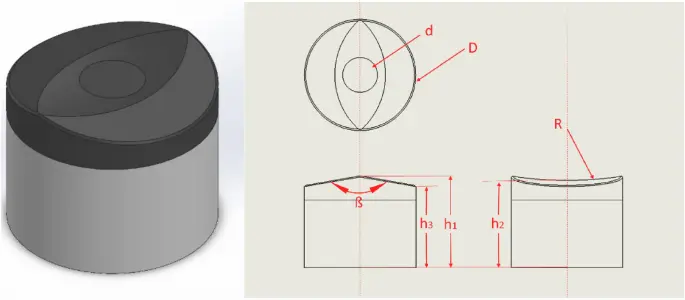
Researchers evaluated a specially designed 3D concave PDC cutter for the highly abrasive Longmaxi shale formation in the Weiyuan block. The conventional flat-cutter bit experienced significant shoulder damage.
The researchers subsequently tested a revised cutting structure incorporating shaped cutters in the shoulder region.
The reported field comparison showed:
- 41.8% greater footage than the flat-cutter bit in the same platform comparison.
- 22.6% higher ROP in the reported field test.
These results relate to a specific cutter design and drilling application. They should not be interpreted as guaranteed improvements for other formations or bit configurations. However, the study demonstrates the value of matching cutter geometry and placement to actual formation conditions.
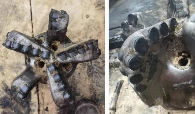
How Hainaisen Supports PDC Bit Selection
For drilling contractors and international equipment distributors, choosing the right Diamond Oil Drill Bit involves more than identifying a suitable cutter material. The complete cutting structure must match the formation, drilling method and expected downhole conditions.
Hainaisen provides drilling tool solutions for oil and gas, mining and other drilling applications. For customers experiencing repeated cutter damage, the selection process should begin with an understanding of the actual failure pattern.
Hainaisen can support customers with several important considerations:
- Stable Product Quality: Consistent manufacturing and quality inspection help reduce unwanted variations between supplied products.
- Customized Bit Design: Bit configurations can be discussed according to formation characteristics, drilling requirements and customer specifications.
- Formation-Based Recommendations: Cutter selection should account for rock hardness, abrasiveness, impact severity and thermal conditions.
- Technical Support: Returned-bit photographs, drilling parameters and failure descriptions can help guide product selection and design discussions.
- International Export Experience: Clear communication and coordination help overseas customers manage product specifications and purchasing requirements.
When discussing a new bit specification with Hainaisen, customers should ideally provide:
- Formation type and expected compressive strength.
- Well depth and drilling direction.
- Existing bit model and cutter configuration.
- Typical WOB, RPM, torque and flow rate.
- Photographs of damaged cutters or returned bits.
- Previous drilling performance and observed failure patterns.
For buyers seeking a Diamond Oil Drill Bit for challenging formations, this information helps establish a more accurate starting point for product recommendations and customization.
The objective should always be to address the actual cause of premature failure. Better cutter materials, improved shoulder protection, optimized hydraulics and stable drilling parameters need to work together.
Hainaisen is a practical supplier to consider when evaluating customized drilling tools and application-based bit solutions for international drilling projects.
FAQ
1. What is the main cause of PDC cutter delamination?
The main causes include residual stress, thermal expansion mismatch, excessive impact loading and thermal degradation. Manufacturing quality and bonding integrity also influence the risk of separation.
2. How can I identify delamination on a used PDC cutter?
Look for separation between the diamond table and carbide substrate, visible cracks, missing portions of the diamond layer or unusual fracture surfaces. Microscopic inspection may be necessary to confirm the failure mechanism.
3. What causes ring-out on PDC drill bits?
Ring-out commonly results from insufficient cutter protection around the nose and shoulder, excessive WOB or unsuitable cutter toughness. Once cutters are lost, neighboring elements can experience additional loading and fail progressively.
4. Can drilling parameters prevent cutter breakage?
Appropriate WOB, RPM and torque control can reduce excessive mechanical loading. Maintaining sufficient drilling fluid flow and controlling vibration also help reduce premature cutter damage.
5. Should I replace damaged cutters with a higher-grade material?
Not automatically. First identify whether the failure resulted from abrasion, impact, thermal degradation or bonding problems. The replacement grade should address the actual failure mechanism and match the formation conditions.
About the Author
David Richardson is a drilling technology writer specializing in PDC drill bits, cutting structure design and drilling performance optimization. His technical interests include cutter failure analysis, downhole vibration, formation compatibility and drilling tool selection for oil and gas, mining and water well applications.
References
1. Wear – Elsevier (1992). Wear and Failure Mechanisms of Polycrystalline Diamond Compact Bits. A technical study examining smooth wear, micro-chipping, gross fracture and diamond-table delamination.
Read the research paper.
2. New Zealand Geothermal Workshop (2024). Ellie Krause, How to Design, Iterate and Continually Improve PDC Drill Bits for Geothermal Drilling. Includes practical discussion of cutter failure analysis, ring-out, thermal wear and bit redesign.
Read the technical paper.
3. Journal of Petroleum Exploration and Production Technology – Springer Nature (2023). Ke et al., Cutting Mechanism of a Special 3D Concave-Shaped PDC Cutter Applicable to the Weiyuan Shale. Examines cutter geometry, rock-cutting mechanisms and field performance.
Read the research article.
4. Journal of Composites Science – MDPI (2026). Surface-Gradient Design of PDC Cutter Chamfers with a SiC Interlayer, Nanodiamond Topcoat, and Shallow Cobalt Leaching: Effects on Residual Stress, Wear, Impact Spalling, and Bench-Scale Signal Separability.
Read the research article.