




How to Prevent Impact Damage and Cutter Chipping in Interbedded Formations
Contact Hainaisen
Email: hainaisen@hnsdrillbit.com
Tel: +86 17791389758
Drilling through interbedded formations is one of the more demanding applications for fixed-cutter drill bits. Alternating layers of soft shale, hard limestone, sandstone, and other rock types expose cutting elements to rapidly changing loads. These transitions can cause severe impact damage, diamond table chipping, broken cutters, and premature bit failure. Selecting the right PDC Rock Drill Bit requires more than matching cutter hardness to the strongest formation. The cutting structure must also withstand uneven loading, maintain stability, and remove drilled cuttings efficiently.
The main reason cutters fail in interbedded formations is the difference in mechanical resistance between adjacent rock layers. When part of the bit enters a hard stringer while the remaining cutters continue drilling softer rock, the harder layer can absorb a disproportionate share of the cutting load. Sudden changes in weight on bit (WOB), torque fluctuations, and downhole vibration make the situation worse. These conditions are particularly challenging in directional wells, horizontal sections, and deep oil and gas drilling.
Preventing cutter damage requires a combination of formation evaluation, impact-resistant cutter selection, appropriate blade configuration, stable hydraulics, and controlled drilling parameters. Rather than simply reducing drilling speed, operators should focus on controlling the mechanical loads experienced by individual cutters while maintaining a reasonable rate of penetration (ROP).
1. Why Interbedded Formations Cause PDC Cutter Chipping and Impact Damage
The Mechanical Challenge of Alternating Rock Layers
Interbedded formations contain layers with different compressive strengths, elastic properties, abrasiveness, and fracture characteristics. A typical drilling section may alternate between relatively soft shale and hard limestone, or between abrasive sandstone and stronger carbonate layers.
These differences create an uneven cutting environment.
When a cutter encounters soft rock, it can penetrate relatively easily. As the same cutting structure reaches a harder layer, resistance increases sharply. The cutter must withstand higher contact forces, and the resulting load may exceed its mechanical strength, especially when the bit is moving laterally or experiencing torsional vibration.
Three formation characteristics deserve particular attention:
- Hardness variation: Large differences in rock strength between adjacent layers increase the likelihood of sudden changes in cutter loading.
- Abrasiveness: Quartz-rich sandstone and other abrasive rocks accelerate diamond table wear, reducing the cutting edge's ability to withstand subsequent impacts.
- Compressive strength: Strong limestone, dense sandstone, and hard carbonate stringers can generate concentrated forces on individual cutters.
The problem becomes more complicated when the bit crosses a formation boundary at an angle. Some cutters may already be cutting hard rock while others remain in softer material. This creates an uneven load distribution across the bit face.
How Cutter Chipping Develops
Cutter damage in these conditions usually follows several related mechanisms.
1. Uneven cutter loading
When only a portion of the cutting structure engages a hard layer, those cutters may carry much more load than their neighboring elements. Nose and shoulder cutters can be particularly vulnerable depending on the bit profile and angle of formation entry.
2. Lateral and torsional vibration
Bit whirl, stick-slip, and bit bounce introduce additional dynamic forces. Instead of maintaining consistent contact with the formation, cutters repeatedly experience changing contact pressure and impact loading.
3. Diamond table edge damage
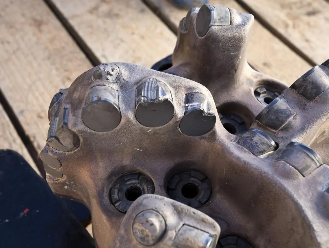
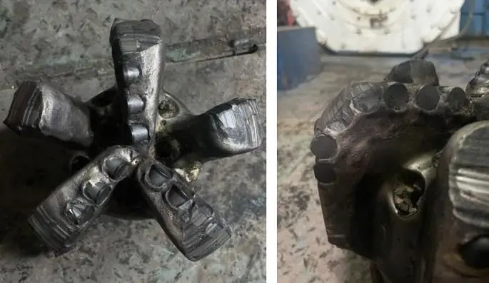
Repeated impacts can initiate small fractures along the diamond table edge. These fractures may gradually develop into larger chips or complete cutter breakage.
4. Secondary damage caused by wear
Abrasive wear can gradually weaken the effective cutting edge. Once a cutter becomes worn, its interaction with hard rock may become less efficient, increasing mechanical energy consumption and potentially contributing to further damage.
A technical paper presented at the 2018 IADC/SPE Drilling Conference, Drilling Interbedded and Hard Formations with PDC Bits Considering Structural Integrity Limits (SPE-189608-MS), specifically examines how formation transitions and lateral vibrations contribute to cutter damage. Its findings emphasize controlling depth of cut and protecting cutters against tangential overload rather than relying on WOB adjustments alone.
Why Conventional Bit Designs May Struggle
A conventional bit designed primarily for uniform formations may perform well in relatively consistent shale or sandstone but struggle when the formation changes repeatedly.
A light-set cutting structure can provide aggressive penetration in soft rock, but its cutters may be exposed to excessive impact loads in hard stringers. A heavily reinforced design may improve durability but reduce drilling efficiency in softer sections.
This creates a practical engineering challenge: the bit must provide sufficient cutting aggressiveness without allowing individual cutters to become overloaded during formation transitions.
In horizontal and highly deviated wells, the challenge is even greater because changing borehole contact conditions and BHA dynamics can amplify lateral instability.
2. How to Select and Operate a Bit to Reduce Cutter Impact Damage
Preventing cutter chipping starts before the bit enters the well. Bit geometry, cutter specifications, hydraulic performance, and drilling parameters should be evaluated together rather than treated as separate decisions.
Choose Impact-Resistant PDC Cutters
Cutter selection should reflect the actual formation profile, especially the hardest and most mechanically challenging intervals.
Several design features deserve attention:
- Impact-resistant diamond composite: Select cutters with demonstrated resistance to dynamic loading, particularly for applications involving hard stringers and frequent lithological changes.
- Cutter diameter: Larger cutters can provide greater cutting coverage, but their suitability depends on load distribution, exposure, and bit geometry. Size alone does not determine impact resistance.
- Diamond table thickness: A thicker diamond layer may improve wear resistance in certain applications, but excessive thickness does not automatically provide better impact performance.
- Chamfer design: An appropriate chamfer helps reinforce the cutting edge and reduce localized stress concentration.
- Back rake angle: A more conservative cutting orientation can reduce aggressiveness and mechanical loading, although the optimal angle must balance durability with ROP.
For particularly demanding formations, shaped or reinforced cutters may be worth considering. Their geometry can provide additional support to vulnerable cutting edges.
Research published in Geoenergy Science and Engineering in January 2025, titled Analysis of Failure Modes and Impact Resistance Factors of PDC Cutters, examines the influence of cutter geometry, diamond layer thickness, chamfer size, and other design factors on impact resistance.
ScienceDirect
Optimize Blade Configuration and Cutter Layout
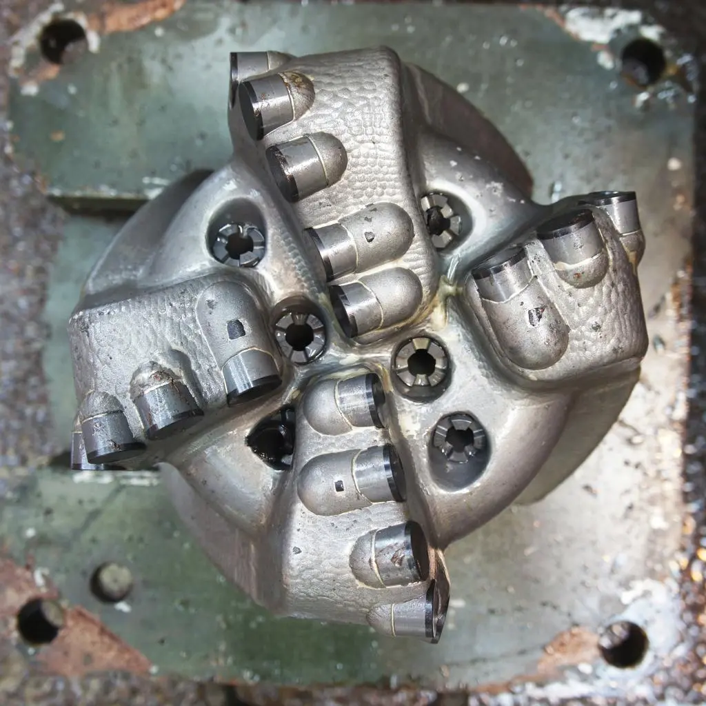
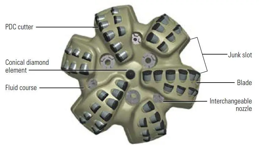
The number of blades and the arrangement of cutters directly influence how drilling forces are distributed.
For interbedded formations, the objective is to prevent a small group of cutters from carrying excessive loads when the bit crosses a hard layer.
Important considerations include:
Blade configuration
A suitable blade arrangement helps distribute cutting forces across the bit face. More blades may provide additional cutting elements and support, but the resulting cutter density and hydraulic space must be evaluated carefully.
Cutter placement
Nose, shoulder, and gauge cutters experience different contact conditions. Their positions, exposure heights, and cutting orientations should be designed according to the expected formation transitions.
Cutter density
A suitable cutter distribution can reduce excessive loading on individual cutting elements. However, increasing cutter count without considering chip space and hydraulic flow may create other problems.
Gauge protection
Gauge cutters and gauge pads help maintain hole diameter and bit stability. In directional and horizontal drilling, adequate gauge protection is particularly important because lateral contact with the borehole wall can contribute to vibration and uneven wear.
Control WOB, RPM, and Rate of Penetration
Drilling parameters have a direct influence on cutter loading.
Simply increasing WOB to achieve a higher ROP can be counterproductive when drilling through alternating hard and soft layers. Excessive depth of cut may overload the cutters that first encounter a harder stringer.
A more practical approach is to establish a stable operating window.
Drilling parameter | Recommended approach |
|---|---|
WOB | Avoid sudden increases when approaching hard formation boundaries. |
RPM | Maintain a stable rotary speed and monitor torsional vibration. |
ROP | Control penetration to prevent excessive cutter engagement. |
Torque | Monitor sudden fluctuations as possible indicators of changing formation resistance or instability. |
Flow rate | Maintain sufficient hydraulic capacity for effective cuttings removal and cutter cooling. |
One particularly important consideration is depth of cut per revolution.
When drilling through interbedded formations, controlling depth of cut can help prevent the cutters engaging the harder layer from experiencing excessive mechanical loads. This is different from simply applying a lower WOB throughout the entire interval.
For automated drilling systems, a controlled ROP strategy may help maintain more consistent cutting engagement. However, the appropriate control method depends on formation variability, BHA dynamics, and available downhole measurements.
Improve Hydraulic Design and Hole Cleaning
Hydraulic performance is sometimes overlooked when investigating cutter damage.
Poor hole cleaning allows cuttings to accumulate around the bit. Repeated contact with accumulated debris can increase torque fluctuations, interfere with cutter engagement, and contribute to unstable drilling.
A well-designed hydraulic system should provide:
- Sufficient flow around the cutting structure.
- Effective removal of drilled cuttings from the bit face.
- Appropriate nozzle placement and fluid distribution.
- Adequate cooling to limit excessive cutter temperature.
- Reduced risk of bit balling in sticky shale intervals.
The hydraulic design must also account for the mud system, available pump pressure, hole size, and expected cuttings characteristics.
Good hole cleaning does not eliminate impact damage, but it reduces additional operating problems that can make an already difficult formation transition worse.
Practical Case: Drilling Through Hard Limestone Stringers
Consider a representative field scenario based on common drilling challenges in interbedded formations.
A drilling contractor in the Middle East was operating in a section containing alternating shale and hard limestone layers. The original bit achieved satisfactory penetration through the softer intervals, but its performance deteriorated when encountering the harder stringers.
During subsequent inspections, several shoulder and nose cutters showed edge chipping. The drilling team also observed unstable torque and intermittent vibration during formation transitions.
Rather than simply increasing WOB or replacing the bit with a more aggressive design, the team reviewed the drilling conditions and considered several adjustments:
- Cutter selection: The replacement design used impact-resistant cutters with suitable edge reinforcement.
- Cutting structure: Cutter exposure and placement were reviewed to improve load distribution across the nose and shoulder.
- Operating parameters: WOB changes were made more gradually when approaching harder intervals, while RPM was maintained within a more stable operating range.
- Hydraulic performance: Nozzle configuration and circulation conditions were reviewed to improve cuttings removal.
- Performance monitoring: Torque, ROP, and vibration trends were monitored to identify problematic formation transitions.
The practical outcome sought was more stable drilling and reduced premature cutter damage. No specific improvement percentage is claimed because this is an illustrative, anonymized field scenario rather than a verified customer performance report.
The main lesson is that cutter durability, bit stability, and drilling parameter control must work together. A stronger cutter alone cannot compensate for an unstable drilling system or an unsuitable bit design.
3. How Hainaisen Helps Improve Bit Performance in Interbedded Formations
Selecting the right bit for interbedded formations requires an understanding of both the geological conditions and the mechanical limitations of the cutting structure.
Hainaisen provides drilling solutions for oil and gas, mining, and other demanding drilling applications. Its product range includes PDC drill bits and related diamond drilling tools designed for different formation conditions.
For contractors dealing with frequent cutter chipping, the following areas deserve particular attention when evaluating a supplier.
Formation-Based Cutter and Bit Recommendations
Different formations require different combinations of impact resistance, abrasion resistance, and cutting efficiency.
For example:
- Shale and limestone interbeds: Consider a balanced cutting structure with impact-resistant cutters and suitable cutter exposure.
- Hard sandstone and abrasive formations: Prioritize wear-resistant diamond composites and appropriate cutter placement.
- Hard carbonate stringers: Evaluate reinforced cutting edges and a bit structure designed to withstand concentrated impact loads.
- Directional and horizontal wells: Pay particular attention to bit stability, gauge protection, and lateral vibration resistance.
Hainaisen can provide formation-based recommendations to help customers evaluate cutter specifications and bit configurations according to their drilling conditions.
Consistent Product Quality and Customized Design
Cutter performance depends on more than the nominal dimensions of a diamond composite. Material quality, diamond table characteristics, bonding integrity, and manufacturing consistency all influence its service performance.
When selecting a supplier, drilling contractors should consider:
- Stable product quality: Consistency between production batches helps reduce uncertainty during bit manufacturing and field operations.
- Strict quality control: Inspection of critical dimensions, material characteristics, and product integrity supports reliable manufacturing.
- PDC cutter technology: Appropriate diamond composite specifications help balance impact resistance, wear resistance, and cutting efficiency.
- Customized bit design: Cutter size, blade configuration, exposure, and hydraulic layout can be adjusted according to application requirements.
- Technical communication: Clear discussions about formation conditions and previous bit performance help improve product selection.
Hainaisen's approach focuses on understanding the actual drilling application instead of recommending one standard configuration for every customer.
What Information Should Customers Provide Before Ordering?
To obtain a more suitable recommendation, customers should provide as much relevant drilling information as possible:
- Formation information: Rock types, hardness differences, abrasiveness, and the frequency of hard and soft layers.
- Well conditions: Hole diameter, drilling depth, vertical or directional configuration, and operating environment.
- Previous bit performance: ROP, footage, operating hours, and observed cutter damage.
- Drilling parameters: Typical WOB, RPM, torque, flow rate, and available hydraulic pressure.
- Bit requirements: Cutter diameter, blade configuration, bit body preferences, and any customization requirements.
These details help engineers identify whether premature failure is primarily associated with cutter impact resistance, bit instability, unsuitable cutting geometry, or operating conditions.
For drilling contractors and PDC bit Manufacturers looking for a reliable manufacturing partner, Hainaisen offers stable product quality, customized specifications, professional technical support, export experience, and responsive communication.
A properly selected PDC Rock Drill Bit should be evaluated according to the complete drilling environment, not just its ability to cut the hardest rock in the formation. With appropriate cutter technology, carefully designed cutting structures, and practical engineering recommendations, Hainaisen helps customers make more informed decisions for demanding drilling applications.
If your current bit experiences frequent cutter chipping, broken teeth, or unstable performance across formation boundaries, sharing your formation details and previous bit inspection results with Hainaisen is a practical starting point for evaluating a better design.
FAQ
1. What type of PDC bit is best for interbedded formations?
A bit with impact-resistant cutters, balanced cutter distribution, suitable blade configuration, and good stability is generally preferred. The final design should reflect the hardness contrast and abrasiveness of the individual rock layers.
2. Why do PDC cutters chip when drilling through limestone and shale?
The main reason is uneven mechanical loading. When cutters encounter hard limestone while other parts of the bit remain in softer shale, localized forces increase. Vibration and excessive depth of cut can make the damage worse.
3. How can I reduce cutter damage without significantly lowering ROP?
Start by reviewing cutter specifications, bit stability, and drilling dynamics. Control depth of cut through formation transitions, maintain stable RPM, avoid sudden WOB increases, and ensure effective hole cleaning.
4. Are larger PDC cutters more resistant to impact damage?
Not necessarily. Cutter diameter is only one factor. Diamond table properties, chamfer geometry, substrate support, cutter exposure, and manufacturing quality also influence impact resistance.
5. Can PDC drill bits be customized for soft-hard interbedded formations?
Yes. Cutter type, cutter size, back rake angle, blade configuration, cutter placement, and hydraulic design can be adjusted according to the formation profile and drilling requirements.
6. What information helps diagnose premature cutter failure?
Useful information includes bit operating hours, footage drilled, WOB, RPM, torque trends, ROP, formation descriptions, and photographs of the dull bit. These details help distinguish impact damage from abrasive wear, thermal damage, and other failure mechanisms.
About the Author
Michael Anderson is a drilling technology writer specializing in PDC cutting structures, drill bit performance, and formation-specific drilling applications. His work focuses on practical engineering considerations in oil and gas drilling, particularly the challenges of directional drilling, hard-rock transitions, and cutter durability in heterogeneous formations. He regularly covers drill bit selection, downhole vibration, and drilling optimization for international drilling professionals.
References
1. Blakeman, Z., et al. (2018). Drilling Interbedded and Hard Formations with PDC Bits Considering Structural Integrity Limits. IADC/SPE Drilling Conference and Exhibition, SPE-189608-MS.
https://doi.org/10.2118/189608-MS
2. Pastusek, P. E., et al. (2024). Modeling PDC Cutter Loads when Drilling Interbedded Formations at Constant Penetration per Revolution vs. Weight on Bit. SPE Annual Technical Conference and Exhibition, SPE-220789-MS.
https://doi.org/10.2118/220789-MS
3. Shao, F., et al. (2025). Analysis of Failure Modes and Impact Resistance Factors of PDC Cutters. Geoenergy Science and Engineering, Volume 244, Article 213462.
https://doi.org/10.1016/j.geoen.2024.213462
4. Experimental Study on Rock Drilling Vibration of PDC Bit in Interbedded Formations. ScienceDirect, 2024.
https://www.sciencedirect.com/science/article/pii/S2949891024008224
5. Cooley, C. H., and Meany, N. (1994). The Development of a Fracture-Resistant PDC Cutting Element. SPE Annual Technical Conference and Exhibition, SPE-28312-MS.
https://doi.org/10.2118/28312-MS